• Start
  • About us
  • Products
    • Fabrics
      • Europe Catalog
      • America Catalog
    • ECO products
    • Accessories
    • Knitwear
  • Regulation
  • Sustainability
  • Vídeos
  • News
    • Fairs
    • New products
    • Newsletter
  • contact
  • English
  • French
  • German
  • Spanish
Search
Menu
Search
Placeholder
ASTM F1930:2023
Back to products
Placeholder
ASTM F955:2021

ASTM F1959:2022

TEST METHOD FOR DETERMINING THE ARC CLASSIFICATION OF CLOTHING MATERIALS

  • DEFINITION
  • DEFINITIONS
  • APPLIANCES
  • SAMPLES
  • TEST
  • RESULTS ANALYSIS
  • ATPV VALUES
  • DETERMINATION OF THE HEAT ATTENUATION FACTOR (HAF)
  • DETERMINATION OF BREAKING ENERGY
  • ARC CLASSIFICATION
  • REPORT

DEFINITION

This test method is used to measure the arc rating of materials intended to be used as flame resistant clothing for workers exposed to electric arcs that would generate heat flux rates of 2100kw/m2 [50 Cal/Cm2s].

The test will measure the arc rating of materials that meet the following requirements: less than 150 mm [6 in] char length and less than 2 s after flame when tested in accordance with test method D6413.

It does not apply to the risks of electrical contact or electric shock.

It is the responsibility of the user of this standard to establish appropriate safety and health practices and determine the applicability of regulatory requirements prior to use.

DEFINITIONS

  • Ablation, n-in arc flash testing, a physical response evidenced by significant erosion or the formation of one or more large holes in one layer of a multilayer system.
  • Eab: The incident energy in a multilayer system that results in a 50% probability of the ablation physical response.
  • Arc rating is expressed in cal/cm2 and is derived from a determined ATPV or EBT value (if a material system exhibits a breakdown response below the ATPV value) derived from a determined ATPV or EBT value (should a system material shows a rupture response below the ATPV value).
  • ATPV: The incident energy on a material or a multilayer system of materials that results in a 50% probability that sufficient heat transfer is anticipated through the test sample to cause the occurrence of a second degree skin burn injury. according to the Stoll5 curve, kW/m2 [cal/cm2].
  • The specimen is considered to exhibit rupture when any hole is at least 0.5 in.2 [1.6 cm2] in area or at least 1.0 in. [2.5 cm] in any dimension. In multi-layered specimens of fire-resistant material, all layers must break to meet the definition.
  • EBT – The incident energy on a material or material system that results in a 50% probability of opening, J/cm2 (cal/cm2).
  • Heat Attenuation Factor, HAF: In arc flash testing, the percentage of incident energy that is blocked by a material at an incident energy level equal to ATPV.
  • Heat flux, n: The thermal intensity indicated by the amount of energy transmitted divided by the area and the time kW/m2 [cal ⁄cm2s].
  • Incident energy (Ei), n—the total thermal energy received at the panel surface as a direct result of an electrical arc.
  • Stoll Curve 5: An Empirical Model of Predicted Second Degree Skin Burn Injury, Also Commonly Known as the Stoll Response.

This test method determines the heat transport response through a material, fabric, or tissue system when exposed to the thermal energy of an electrical arc. This heat transport response is assessed against the Stoll curve, an approximate human tissue tolerance predictive model that projects the occurrence of a second degree burn injury.

During this procedure, the amount of thermal energy transferred by the tested material is measured during and after exposure to an electric arc.

Material performance for this procedure is determined from the amount of heat transferred by and through the tested material.

The heat transfer data determined by this test method is the basis of the arc classification for the material.

The arc rating determined by this test method is the amount of energy that predicts a 50% chance of a second degree burn as determined by the Stoll Curve or rupture (if the sample shows rupture before the arc prediction is reached). skin burn injury).

The response of the material should be described in more detail by recording the observed effects of arc flash exposure on the specimens.

APPLIANCES

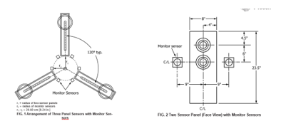
General arrangement to determine arc classification using three panels of two sensors and monitoring sensors. The test apparatus will consist of a supply bus, an arc controller, a recorder, arc electrodes, three panels of two sensors, and monitoring sensors.

  1. Two-Sensor Panel Arrangement: Three two-sensor panels will be used for each test and will be equally spaced as shown in the figure. Each two-sensor panel shall have two monitoring sensors. A monitoring sensor will be placed on each side of the panel of two sensors like figure 2.
  2. Panel Construction: Each two-sensor panel and each monitor sensor bracket shall be constructed of heat-resistant, non-conductive material with a thermal conductivity value of <0.15 W/mK, high-temperature stability, and resistance to thermal shock , The board must have a thickness of 1.3 cm or more.
  3. Each panel of 2 sensors should measure 20.3 x 54.6 cm x 1.3 cm as shown in Figure 2.
  4. Each sensor must be mounted flush with the surface of the mounting plate.
  5. Additional calorimeters are permitted for experimental purposes.

SAMPLES

  • Post-washed sample is at least 61.0 cm [26 inches] long and at least 30.5 cm [12 inches] wide. The length direction should be cut in the direction of the warp or column of the material.
  • Wash required amount following AATCC Procedure 135, Procedure 3, IV, A, III.
  • Wash three times following this procedure.
  • After three wash cycles, tumble dry
  • Calibration prior test, calorimeter verification, arc exposure, panels and sensors.

TEST

  • Test parameters should be 8 6 1 kA arc current, 12 in. (30.5 cm) electrode gap and stainless steel electrodes.
  • Each test shall consist of three specimens of the same material, one for each of the three panels of two sensors.
  • To evaluate a single sample of a material, a series of at least seven tests must be performed over a range of incident energies. A minimum of 20 average results is required for an ATPV determination.
  • Incident energy range must be achieved by increasing or decreasing arc duration (cycles).
  • The incident energy measured on at least 15% of the two exposed sensor panels should result in values ​​that always exceed the second degree burn injury criteria predicted by the Stoll curve.
  • The incident energy measured on at least 15% of the two exposed sensor panels should result in values ​​that never exceed the second degree burn injury criteria predicted by the Stoll curve.
  • The incident energy measured on at least 50% of the two exposed sensor panels should result in values ​​that fill approximately equally within 620% of the final ATPV
  • Values ​​in this energy range often have mixed results: some values ​​pass and some do not pass the Stoll criteria.
  • All data points are valid unless the temperature of the copper calorimeter exceeds 400ºC.
  • Specimens exhibiting burst or sub-layer ignition are valid data points for ATPV determination.
  • If two or more occurrences of material failure are observed with incident energies below a value 20% above the ATPV determination, a failure response should be determined. In this case, more than seven tests may be required before the breaking response can be assessed.
  • An iterative process will be needed to achieve the requirement that 50% of the data points be within 20% of the ATPV material systems.
  • After completing the first two arc exposures an estimated ATPV can be determined.

Determination of heat transfer with the three-sensor panel test:

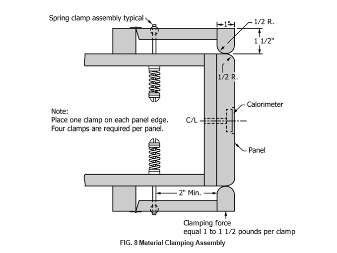
  • The sample must be attached to the panel without stretching the material and in a manner that allows the sample to shrink during arc exposure.
  • Expose the specimens to the electric arc taking into account all the safety measures indicated
  • Once the arc initiation point is determined, the temperature data collected from the calorimeters before and up to the initiation point is averaged to obtain an initial calorimeter temperature, initial (°C) for each respective sensor.
  • The total incident thermal energy as a function of time on each panel is determined by averaging the results of the respective pair of monitor thermal energy sensors at each time interval.
  • The total thermal energy transmitted through the specimen to the panel as a function of time for each exposed panel is determined by averaging the results of the panel’s respective pair of thermal energy sensors at each time interval.

RESULTS ANALYSIS

  • Heat Transfer: For each sensor curve, plot the difference between the curve and a line drawn from the start of the data stream to some point in the rising temperature region of the curve. Find the maximum of this difference graph. The point at which this maximum occurs is the best estimate of arc initiation time for that sensor. These arc start points are usually very consistent within a test, but the median of these points or of all sensors should be used as the start point for all sensors.
  • Plot of panel sensor responses: The average panel calorimeter sensor response is plotted for each panel as a function of time
  • Incident Energy Monitor Sensor Responses (Ei): Calculate the average value of the monitor sensor values ​​from each panel to determine the average incident energy for each respective panel. Record the maximum thermal energy value of the monitor sensor pair averaged for each panel during the data collection period. The resulting maximum values ​​are the incident heat energies, Ei, delivered to each respective panel.
  • Predicted Determination of Second Degree Skin Burn Injury (Stoll Curve Comparison): The average time-dependent thermal energy response for each panel (of the meters below the sample being tested) is compared to the empirical model second degree skin burn injury predicted by the Stoll Curve:
  • Record a value of 1 for each panel that ever exceeds the Stoll criteria, and a value of 0 for those that do not.

ATPV VALUES

  • Determining Arc Thermal Performance Values ​​(ATPV): Use a minimum of 20 measured panel responses to calculate an ATPV value. If more than 20 points are collected during a specific test exposure sequence, all valid results will be used to determine the ATPV.
  • Perform a nominal logistic regression on the resulting test data. The average maximum response of the incident energy monitor sensor is used as the continuous variable, X for each panel. The corresponding nominal binary Y value response is the average response of the panel sensor, exceeding = 1/not exceeding = 0, Stoll’s criterion
  • Use the values ​​of slope and intercept determined by logistic regression to calculate (inverse prediction) the value of the 50% probability of exceeding the Stoll curve criterion. This is the ATPV result, or the incident energy value that would cross the Stoll curve criteria.

DETERMINATION OF THE HEAT ATTENUATION FACTOR (HAF)

  • Determine the maximum average thermal energy response for each of the panels from the generated graphs and divide these responses by their respective maximum average incident energy monitor sensor responses.
  • Label each of these values ​​as E transmitted (fraction of the incident energy that is transmitted through the sample) for each panel.
  • The HAF factor is then determined by averaging all the haf values. At least 20 data points representing 20 panels will be used.
  • Calculate the standard deviation of the points, the standard error of the average (given by the ratio of the standard deviation to the square root of the number of panels used) and the 95% confidence interval.

DETERMINATION OF BREAKING ENERGY

  • The breaking energy response is assessed in a similar manner to an ATPV determination. This is done using the breakdown information from the test panel together with the incident energy, Ei. Responses from rupture-proof panels shall be distributed so that at least 15% of panels seeing lower incident energy values ​​do not show rupture, at least 15% of panels seeing higher incident energy values always open and 50-70% of the panels have incident power. energy values ​​that are within 20% of the determined EBT value. If there is insufficient data in these ranges, perform additional panel tests in the respective incident energy range and record the response of the material. A minimum of 20 data values ​​with distributed incident energy values ​​is required,
  • The following technique can be used to determine the breakdown response of a materials system independent of the resulting incident energy and its relationship to the Stoll curve or ATPV determination. This can be useful to determine the failure response of the material in multilayer systems.
  • Record a value of 1 for each panel that ever shows breakage and a value of 0 for those that do not.
  • Perform nominal logistic regression on the resulting test data. The maximum average response of the incident energy monitor sensor is used as the continuous variable, X. The corresponding nominal binary Y value response is the break response of the panel material, break = 1/no break = 0.
  • Use the determined values ​​of slope and intercept from the logistic regression to calculate (inverse prediction) the 50% probability value of material failure. This is the EBT value, or the value of the incident energy that alone would predict a breakout.

ARC CLASSIFICATION

  • Report the ATPV as the arc classification of the material samples (ATPV), if no breakout occurs below or within the mixing zone during the ATPV determination. If not, perform enough panel tests to allow determination of the EBT value.
  • If an EBT value is determined and found to be equal to or less than a given ATPV, then the EBT value shall be reported as the Arc Rating value of the tested system and noted on the test report as Arc Rating (EBT).
  • If an EBT value is determined and it is above a given ATPV, then the ATPV result shall be reported as the arc rating (ATPV) of the sample tested.

REPORT

  • sample data
  • Conditions of each test including:
    • test number
    • maximum arc current
    • arc space
    • arc duration
    • arc energy and arc current diagram.
  • Test data including;
    • test number
    • test tube
    • layer order
    • distance from the center line of the arc to the surface of the panel
    • graph of the response of the two monitor sensors and the two panel sensors for each panel test
    • graph of the average response of the two panel sensors and the two monitor sensors for each panel test
    • arc classification of ATPV or EBT
    • heat attenuation factor (HAF) and HAF 95% confidence intervals
    • HAF graph in Ei
    • plot of incident energy distribution Ei from bare shot analysis, for multilayer systems
    • weight of each of the layers tested
    • the rupture value, EBT, if determined in addition to ATPV, but not used as the arc rating
    • the value of ignition, ignition50
    • the plot of probability of burn injury versus Ei used for the determination of ATPV
    • the Plot of Failure Probability vs. Ei used for EBT determination (if determined), and the underlying Ignition Probability Plot of er vs. Ei used to determine bottom layer ignition (if determined).
  • Arc ratings (ATPV or EBT) below 10 cal/cm2 must be reported to an accuracy of 0.1 cal/cm2. Arc rated values ​​(ATPV or EBT) above 10 cal/cm2 must be reported to the nearest 1 cal/cm2.
Compare
Add to wishlist
Category: Normative

Development and innovation of technical fabrics: THAT IS LENARD. Founded in 1996 by people with extensive experience in the textile sector, it has stood out since its beginning for a strong commitment to innovation and personal protection through the use of new fibers and manufacturing methods with the most advanced technology. Its wide range of fabrics offers protection for different sectors, complying with the requirements established by international certifications.

Latest news
  • Newsletter march 2025
    13 de March de 2025 No Comments
  • Newsletter february 2025
    12 de February de 2025 No Comments
  • Visibility and Protection: Discover the 809 Xispal RS
    29 de January de 2025 No Comments
  • INTERSEC DUBAI
    10 de January de 2025 No Comments

LENARD BCN, S.L.

Avda. Aragón nº37 - 22520 Fraga (Huesca)
info@lenard.tech
How to get

CENTRO OPERATIVO / HEADQUARTERS

Pol. Ind. Sot dels Pradals
C/ Sabadell, 3
08500 - Vic (Barcelona) Spain
How to get

LENARD MX, S de RL de CV

Rio Atoyac 30. Parque Industrial Empresarial Cuautlancingo
Cuautlancingo, 72730 Puebla (México)
+52 222 2319969
jisanchez@lenard.tech
How to get

LENARD USA CORP

2655-Lejeune Rd., Suite 810
Coral Gables, FL. 33134 (USA
+52 222 2319969
fcastejon@lenard.tech
How to get

LENARD Diseño web: Infoactiva't.
Aviso legal | Política de privacidad | Política de cookies
  • Start
  • About us
  • Products
    • Fabrics
      • Europe Catalog
      • America Catalog
    • ECO products
    • Accessories
    • Knitwear
  • Regulation
  • Sustainability
  • Vídeos
  • News
    • Fairs
    • New products
    • Newsletter
  • contact
  • English
  • French
  • German
  • Spanish
  • Wishlist
  • Compare
  • Login / Register
Start typing to see products you are looking for.

We are using cookies to give you the best experience on our website.

You can find out more about which cookies we are using or switch them off in .

Privacy Overview

This website uses cookies so that we can provide you with the best user experience possible. Cookie information is stored in your browser and performs functions such as recognising you when you return to our website and helping our team to understand which sections of the website you find most interesting and useful.

Strictly Necessary Cookies

Strictly Necessary Cookie should be enabled at all times so that we can save your preferences for cookie settings.

If you disable this cookie, we will not be able to save your preferences. This means that every time you visit this website you will need to enable or disable cookies again.

3rd Party Cookies

This website uses Google Analytics to collect anonymous information such as the number of visitors to the site, and the most popular pages.

Keeping this cookie enabled helps us to improve our website.

Please enable Strictly Necessary Cookies first so that we can save your preferences!